2.2.4 Fibre Refractive Index Profiles
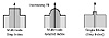
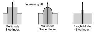
Figure 19. Fibre Refractive Index Profiles
Figure 19 shows the refractive index profiles of some different types of fibre.
RI Profile of Multimode Step-Index Fibre
- Today’s standard MM SI fibre has a core diameter of either 62.5 or 50 microns with an overall cladding diameter in either case of 125 microns. Thus it is referred to as 50/125 or 62.5/125 micron fibre.
- Usually the core is SiO2 doped with about 4% of GeO2. The cladding is usually just pure silica. There is an abrupt change in refractive index between core and cladding.
- The bandwidth.distance product is a measure of the signal carrying capacity of the fibre. This is discussed further in 7.6.1, “Maximum Propagation Distance on Multimode Fibre” on page 335. The bandwidth.distance product for standard step index multimode fibre varies between about 15 MHz/km and 50 MHz/km depending on the wavelength in use, the core diameter and the RI contrast between core and cladding.
RI Profile of Multimode Graded Index Fibre
- Graded index fibre has the same dimensions as step index fibre. The refractive index of the core changes slowly between the fibre axis and the cladding. This is achieved by using a varying level of dopant across the diameter of the core. Note the gradations are not linear - they follow a “parabolic” index profile. It is important to realise that GI fibre is relatively difficult to make and is therefore significantly more expensive than step index fibre (either MM or SM).
- The usual bandwidth.distance product for 62.5 micron GI MM fibre is 500 MHz/km at 1300 nm. In the 800 nm band the bandwidth.distance product is typically much less at 160 MHz/km. For MM GI fibre with a core diameter of 50 microns the bandwidth.distance product is 700 MHz/km (again at 1300 nm). Recently (1997) MM GI fibre with significantly improved characteristics has become available. A bandwidth.distance product figure for 62.5 micron fibre is advertised as 1000 MHz/km and for 50 micron fibre of 1,200 MHz/km. This is a result of improved fibre manufacturing techniques and better process control. Of course these fibres are considered “premium” fibres and are priced accordingly.
RI Profile of Single-Mode Fibre
- Single-mode fibre is characterised by its narrow core size. This is done to ensure that only one mode (well, actually two if you count the two orthogonal polarisations as separate modes) can propagate. The key parameter of SM fibre is not the core size but rather the “Mode Field Diameter”. (This is discussed further in: 2.4.1.1, “Mode Field Diameter (MFD) and Spot Size” on page 57.)
- Core size is usually between 8 and 10 microns although special purpose SM fibres are often used with core sizes of as low as 4 microns.
- The RI difference between core and cladding is typically very small (around .01). This is done to help minimise attenuation. You can achieve the index difference either by doping the core to raise its RI (say with GeO2) or by doping the cladding (say with fluoride) to lower its RI. Dopants in both core and cladding affect attenuation and therefore it’s not a simple thing to decide. There are many different core and cladding compositions in use. Bandwidth.distance product is not a relevant concept for single-mode fibre as there is no modal dispersion (although there is chromatic dispersion).
The refractive index of fibres is changed and manipulated by adding various “dopants” to the basic SiO2 glass. These can have various effects:
- • Some dopants increase the refractive index and others decrease it. This is the primary reason we use dopants.
- • All dopants increase attenuation of the fibre. Thus dopants are to be avoided (or at least minimised) if attenuation is important for the fibre’s application. It is almost always very important.
We might expect that since the light travels in the core that dopant levels in the cladding may not make too much difference. Wrong! In single-mode fibre a quite large proportion of the optical power (electromagnetic field) travels in the cladding. In single-mode fibre attenuation and speed of propagation are strongly influenced by the characteristics of the cladding glass. In multimode graded index fibre the core is doped anyway (albeit at different levels) so (for multimode) it is an issue even in the core.
In multimode step-index fibre there is an “evanescent field” set up in the cladding every time a ray is reflected. This is an electromagnetic field and is affected by the attenuation characteristics of the cladding.
- • If we use a dopant at too high a level not only does it change the refractive index of the glass but it also changes the coefficient of expansion. This means that in operational conditions if we use too much dopant the cladding may crack away from the core.
2.2.4.1 Coating
During manufacture fibre is usually coated with a very thin layer of plastic bonded closely to the cladding. This is often referred to as the “jacket”. It is applied as a continuous process as the fibre is drawn. There are two main reasons for this:
- 1. To prevent water from diffusing into the fibre. Water can cause micro-cracking of the surface. In addition the -OH group is a major source of attenuation due to absorption.
- 2. If a plastic with a higher refractive index than the cladding glass is used this helps to guide unwanted “cladding modes” out of the fibre.
Secondary functions of the coating are that it is usually coloured so that individual fibres can be identified. In loose-tube or gel-filled cables multiple fibres are often packed close together in a common sheath and there is a need to identify which is which. In addition it makes the fibre thicker, easier to handle and less susceptible to damage in handling.
Standard coated fibre has a diameter of 250 microns and thus the coating is 62.5 microns thick. Of course the individual fibre is usually further enclosed in a plastic sheath before integration with other fibres and components into a cable.
2.3 Light Propagation in Multimode Fibre
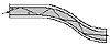
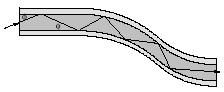
Figure 20. Light Propagation in Multimode Fibre. Light is bound within the fibre due to the phenomena of “ total internal reflection” which takes place at the interface between the core of the fibre and the cladding.
The key feature of light propagation in a fibre is that the fibre may bend around corners. Provided the bend radius is not too tight (2 cm is about the minimum for most multimode fibres) the light will follow the fibre and will propagate without loss due to the bends. This phenomena is called “total internal reflection”. A ray of light entering the fibre is guided along the fibre because it bounces off the interface between the core and the (lower refractive index) cladding. Light is said to be “bound” within the fibre.
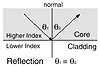
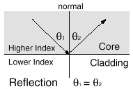
Figure 21. Reflection
If we consider the propagation of a “ray” in a multimode step index fibre we can analyse the situation quite easily with the “laws of elementary physics”.
- “The angle of incidence is equal to the angle of reflection.”
This is illustrated in Figure 21. This means that θ1 = θ2.
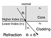
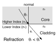
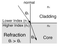
Figure 22. Refraction
The important thing to realise about propagation along a fibre is that not all light can propagate this way. The angle of incidence of the ray with the core-cladding interface (the angle φ in Figure 20 on page 39) must be quite small or else the ray will pass through into the cladding and (after a while) will leave the fibre.
2.3.1 Snell’s Law
In order to understand ray propagation in a fibre we need one more law from high school physics. This is Snell’s law. Referring to Figure 22 and Figure 23:
n1 sin θ1 = n2 sin θ2
Where n denotes the refractive index of the material.
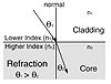
Figure 23. Refraction (2)
Notice here that:
- 1. The angle θ is the angle between incident ray and an imaginary line normal to the plane of the core-cladding boundary. This is counter to intuition but the accepted convention.
- 2. When light passes from material of higher refractive index to a material of lower index the (refracted) angle θ gets larger.
- 3. When light passes from material of lower refractive index to a material of higher index the (refracted) angle θ becomes smaller.